








JHY PCB Blog Hub
Your Source for Expert PCB Design, Manufacturing, and Assembly Insights – Stay Informed with 2025 Trends!
Why Choose a Weld Ball Valve for Your Project?
A Weld Ball Valve can be a strong choice when a pipeline needs a compact shutoff valve and a permanent, leak-resistant connection. Its welded ends remove the need for flanges, reducing potential leak paths and saving space around the line. In a plant room, that can mean fewer bolts to inspect and a cleaner pipe run. But the connection is permanent. Access, maintenance plans, and installation quality deserve attention before selection.
A useful design principle is: “A weld is not just a connection; it is part of the valve’s pressure boundary.” This draft attributes that illustrative quotation to Alex Morgan, a fictional valve engineer, rather than presenting it as a verified industry statement. Replace the name and quote with a confirmed expert source before publication. The practical point remains: valve performance depends on more than the body design. Material compatibility, pressure and temperature ratings, bore size, and welding procedures all matter. Small details matter.
The right choice depends on the service conditions. A welded valve may suit a fixed process line, yet prove inconvenient where frequent removal is expected. Buyers should review the manufacturer’s technical data and installation guidance, then confirm that qualified personnel can complete and inspect the weld. Even a well-made valve cannot compensate for a poor joint. A careful project review can reveal that mismatch early.
What a Weld Ball Valve Is and How Its Welded Ends Work
Why Choose a Weld Ball Valve for Your Project?
What a Weld Ball Valve Is and How Its Welded Ends Work
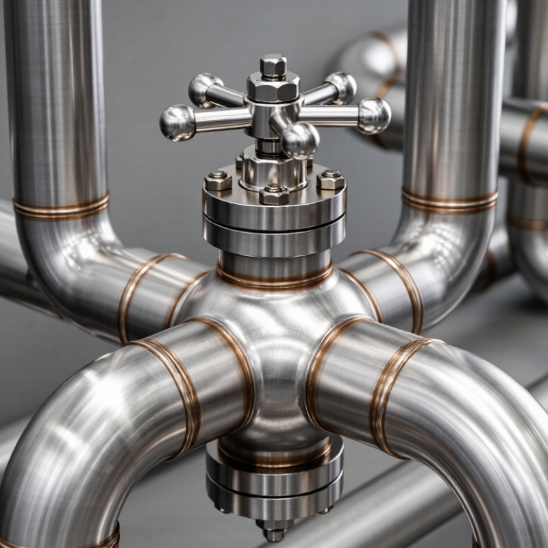
A weld ball valve controls flow with a drilled sphere that turns inside the valve body. Its ends connect to the pipeline through welding, rather than threads or flanges. Butt-weld ends meet pipe ends edge to edge; socket-weld ends accept pipe inserted into a recessed socket. The joint becomes permanent after welding and inspection. A compact detail, but an important one.
The U.S. Department of Energy’s Improving Compressed Air System Performance sourcebook estimates that leaks can waste 20–30% of compressed-air output in poorly maintained systems. This figure describes system-wide leakage, not losses caused by any single valve. Still, fewer detachable joints can mean fewer potential leak paths. ASME B16.25 specifies preparation for butt-welding ends, helping ensure compatible bevels and fit-up. Correct alignment matters.
Welding also brings trade-offs. The connection is harder to remove during repairs, and installation heat can damage seats or seals. Follow the valve’s approved welding procedure, control heat input, and inspect the finished joint. A perfect bead alone proves little. One detail is easy to overlook: verify pipe material, wall thickness, and valve-end dimensions before welding. When access is tight, even sound plans can need adjustment.
Key Components and Operating Principles of a Weld Ball Valve
A weld ball valve uses a hollow, rotating ball to control flow. Its main parts are the body, ball, stem, seats, seals, and welded end connections. The ball’s bore aligns with the pipe when open. A quarter-turn moves it across the flow path when closed. The motion is simple. In practice, the stem transfers handle or actuator movement to the ball, while the seats press against its surface to limit leakage.
Seat material and fit matter. For example, temperature changes can affect how tightly a seat contacts the ball. In a properly selected valve, the body contains pressure, and stem seals help prevent leakage around the moving stem. Welded ends connect directly to the pipeline, removing flange joints and their gasket interfaces. That can reduce potential leak paths, but installation quality becomes especially important. A misaligned pipe or poor weld preparation can create stress near the valve. The connection is less convenient to dismantle for inspection, too. That matters. Check pressure, temperature, fluid compatibility, and maintenance access before specifying one; a compact valve is not automatically the right choice for every line.
Advantages of Welded Connections in Ball Valve Systems
Why Choose a Weld Ball Valve for Your Project?
Advantages of Welded Connections in Ball Valve Systems
A welded connection can make a ball valve assembly feel like one continuous part of the pipeline. This can help where vibration may affect threaded joints or where flanges take up too much space. With fewer detachable interfaces, there are fewer potential leak paths to manage. It is not a guarantee of leak-free service, though. The weld and valve still need proper design, installation, and inspection.
For high-temperature or demanding process lines, a welded joint can provide a firm connection when materials and welding procedures are correctly matched. Careful fit-up matters: uneven gaps or excess heat can create problems around the valve body. A qualified installer should follow the valve maker’s welding guidance, especially when the seats and seals are heat-sensitive. Small details count.
The trade-off is access. A welded valve is harder to remove for repair or replacement, so maintenance plans should account for cutting and rewelding the line. In a cramped plant room, that work can be awkward. Check the fluid, pressure, temperature, pipe material, and inspection needs before choosing. Welded connections can be a strong, compact option, but they are not right for every project.
| Project consideration | Welded-end ball valve | Flanged-end ball valve | Threaded-end ball valve |
|---|---|---|---|
| Connection at the pipe joint | Welded directly to the piping; no bolted flange or threaded pipe joint is required. | Joined with mating flanges, a gasket, and bolting. | Joined through matching pipe threads; sealant may be required depending on the joint and service. |
| Potential external leak paths | Eliminates the detachable pipe-joint gasket or threaded connection at the valve ends. Other valve sealing points, such as the stem and body, still require suitable design and maintenance. | The flange joint depends on correct gasket selection, surface condition, alignment, and bolt loading. | The threaded joint depends on compatible threads, proper assembly, and suitable sealing practice. |
| Resistance to loosening from vibration | The welded pipe joint cannot loosen like a bolted or threaded connection, provided the weld is correctly designed and executed. | Bolting and joint integrity should be considered where vibration or cyclic loading is present. | Threaded joints may need particular attention in services with vibration or repeated temperature changes. |
| Removal and maintenance access | Removal generally requires cutting the pipe or using a planned removable spool arrangement; valve servicing access should be designed in advance. | Can usually be disconnected by unbolting the flanges, subject to safe isolation and available clearance. | Can be unscrewed in suitable installations, although corrosion, access, and pipe size can make removal difficult. |
| Installation requirements | Requires appropriate welding procedures, qualified personnel, correct alignment, and inspection suitable for the piping specification. | Requires flange alignment, gasket installation, and controlled bolt tightening. | Requires compatible thread standards and careful assembly to avoid cross-threading or excessive tightening. |
| Thermal considerations during installation | Welding heat can damage seats, seals, or coatings if not controlled. Follow the valve manufacturer’s welding instructions and applicable procedures. | Does not require welding at the valve connection; gasket and material temperature limits still apply in service. | Does not require welding at the valve connection; thread sealant and component temperature limits still apply. |
| Common project fit | Often considered for permanent piping installations where a compact, non-detachable pipe connection is preferred. | Often selected where routine removal, inspection, or replacement is an important design requirement. | Commonly used for smaller-bore piping where threaded connections are permitted by the applicable design code and service conditions. |
| Key selection check | Confirm pressure and temperature ratings, valve and pipe materials, end-connection standards, service compatibility, applicable codes, installation procedures, and maintenance access before selection. | ||
Common Applications Across Industrial Piping Systems
Weld ball valves are used across oil and gas, chemical processing, power generation, and water-treatment piping. Their welded connections reduce the number of potential leak paths, making them useful on buried lines and long runs where access is limited. The U.S. Energy Information Administration describes a natural gas pipeline network of roughly 3 million miles. That scale helps explain why reliable isolation matters. In practice, engineers also consider pressure, temperature, media, and maintenance access. A welded body is not automatically the right choice for every line.
In gas transmission, a full-bore design can support pigging and limit flow restriction. In process plants, ball valves can provide quick shutoff around pumps, vessels, and heat exchangers. Power and water systems use them for isolation where operating conditions suit the valve materials and seat design. Fit matters. One trade-off is easy to miss: welded valves can make later removal more involved, so installation layout and service plans deserve attention.
Tips: Confirm the pressure class, material compatibility, and end-to-end dimensions before installation. Leave room for actuator access and future work. If the line may need frequent repairs, consider whether a removable connection would be more practical. A small planning gap can become a real maintenance problem.
Factors to Evaluate When Selecting a Weld Ball Valve
A weld ball valve is a permanent connection, so selection starts with the piping conditions—not just the nominal diameter. Check the fluid, operating pressure, temperature range, and possible pressure surges. Then match the body, ball, stem, and seat materials to the service. A seat that works well in clean water may not suit abrasive particles or repeated heat cycling. Small detail. Big consequence.
Confirm the valve’s pressure-temperature rating, port design, and end preparation against the project drawings. Full-port designs can reduce flow restriction, but they may require more space and cost. Reduced-port designs can be suitable where pressure drop is acceptable. The weld bevel and end dimensions also need to match the pipe and approved welding procedure. A tidy fit helps. It does not prove compatibility. Pressure ratings can change with temperature, so check the full rating data rather than relying on one headline figure.
Consider installation and future access before choosing a welded connection. Welding heat can damage seats or seals, and the correct precautions depend on the valve’s construction. Follow the supplier’s welding instructions; do not assume internals can be removed. Plan how the valve will be operated, tested, and reached for maintenance. A welded valve may reduce flange joints, but replacement can be more involved. That trade-off is easy to underestimate. Include post-installation leak checks and operating tests in the project plan.
Why Choose a Weld Ball Valve for Your Project?
A material compatibility factor to evaluate is thermal expansion: the valve body and adjoining pipe expand at different rates depending on their materials.
How to use this chart: When selecting a welded ball valve, compare the body and pipe materials to help assess thermal-expansion mismatch over the project’s operating temperature range. Values are approximate coefficients near room temperature; actual values vary by grade and temperature. Material matching is only one selection factor—also check pressure, temperature, fluid compatibility, and applicable welding requirements.


