











JHY PCB Blog Hub

Your Source for Expert PCB Design, Manufacturing, and Assembly Insights – Stay Informed with 2025 Trends!

10 Tips for Choosing the Right Grounding Kits

Choosing the right Grounding Kits is not a simple matter of selecting the lowest price or the largest conductor. A reliable choice begins with the installation itself: cable size, fault current, enclosure material, vibration, moisture, and available space. In a control cabinet, a small bonding jumper may need to bridge a painted panel. Outdoors, a kit may face rain, salt spray, temperature changes, and repeated maintenance. These details matter.

John D. McDonald, an IEEE Fellow and recognized power-engineering authority, offers a useful principle: “Grounding must be designed as part of the entire electrical system.” That idea should guide every purchasing decision. A kit can look strong on a product page and still fail to fit the actual connection point. Sometimes, the overlooked washer causes the problem. Small details matter.

This guide presents 10 practical tips for choosing Grounding Kits with greater confidence. It considers material compatibility, conductor capacity, corrosion resistance, installation method, certification, and long-term inspection. It also encourages readers to question familiar assumptions. Copper is not automatically the best option. A higher current rating does not always mean better performance. Manufacturer instructions can be incomplete, too.

Experienced electricians verify dimensions before opening the package. They check whether the lug accepts the conductor. They inspect contact surfaces for paint, oxidation, or burrs. They also confirm that the selected kit matches local electrical requirements and the equipment manufacturer’s specifications. Conditions vary. No checklist replaces competent technical judgment.

The goal is not merely to create an electrical connection. It is to establish a dependable path for fault current, reduce touch-voltage risk, and support safe system operation over time.
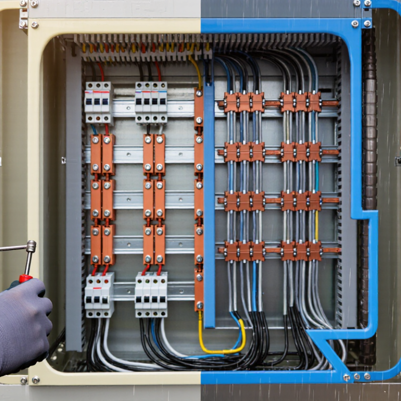
10 Tips for Choosing the Right Grounding Kits

Define the Grounding Requirements for Your Application

10 Tips for Choosing the Right Grounding Kits

Define the Grounding Requirements for Your Application

Before choosing a grounding kit, define what the installation must safely control. Identify the system voltage, available fault current, equipment type, and connection point. Also record whether the kit protects a building, a machine, a cable tray, or temporary equipment. These details shape conductor size, clamp design, electrode selection, and inspection access. Guesswork is expensive. In field inspections, I have seen tidy installations fail because the grounding path was never calculated.

Measure soil resistivity when the grounding electrode depends on local earth conditions. Dry sand, wet clay, crushed rock, and buried steel can produce very different readings. Check expected fault duration, temperature, mechanical stress, and exposure to chemicals or salt. A kit used outdoors may need stronger corrosion resistance than one inside a clean electrical room. Do not size by appearance. Verify conductor cross-section, short-circuit withstand, connector torque, and compatibility with the electrode material. Local electrical rules and project specifications should control the final selection.

During review, ask how the connection will be installed and tested, not merely whether every part is included. Clear access matters. A buried joint that cannot be inspected may pass installation day and create uncertainty later. Photograph the route, record test values, and label disconnected or isolated sections. I prefer leaving a small margin for unusual fault conditions, though excessive material can hide a poor design. That balance deserves a second look.

Evaluate Grounding Kit Materials and Construction Quality

Evaluate Grounding Kit Materials and Construction Quality

Material selection decides whether a grounding kit remains dependable after years of moisture, heat, and vibration. Copper offers excellent conductivity, while tinned copper improves resistance to surface corrosion. Stainless steel adds mechanical strength, but it may create galvanic concerns when paired carelessly with copper. The NACE IMPACT study estimated global corrosion costs at about $2.5 trillion, or 3.4% of worldwide economic output. That figure makes surface protection more than a cosmetic detail.

Look closely at every connection. Strands should be uniform, flexible, and free from broken wires. Clamps need clean threads and stable contact surfaces. Crimped terminals should show consistent compression, not loose edges or deep cracks. IEC 62561-1 defines performance requirements for lightning protection connection components, including mechanical and electrical tests. IEEE Std 80 also emphasizes safe grounding performance through measured grid resistance and touch-voltage control.

Small defects matter.

Inspect plating thickness, seal quality, and labeling before installation. Ask for material certificates, test records, and torque guidance. A kit that looks solid may still fail under repeated thermal cycling. I have found visual checks useful, but they are not enough. Installation errors remain a stubborn weakness. Recheck the finished joint after tightening, especially where dissimilar metals meet. The best construction combines conductive materials, controlled manufacturing, and evidence that testing was actually completed.

Match Kit Specifications to Conductors and Equipment

Choosing the right grounding kit starts with the conductor, not the package label. Match the kit to the conductor’s material, diameter, strand pattern, and insulation type. Copper and aluminum require different contact surfaces and corrosion controls. A kit that fits loosely can create heat, movement, and unreliable fault-current paths.

Tip: Measure the conductor on site. Do not rely only on old drawings. Confirm the equipment’s grounding point, available space, and connection method. Flat bars, threaded holes, and painted enclosures may need different hardware. Check the equipment manual and current installation standards before selecting components. Small details matter.

Tip: Compare the kit’s rated conductor range with the actual cable.

Tip: Verify the clamp fits the equipment shape.

Tip: Check clearance around covers and moving parts.

Tip: Confirm compatible metals.

Tip: Use the specified torque.

In field work, I have seen installers choose a kit because it looked strong. That was not enough.

Tip: Inspect contact surfaces for paint, dirt, or oxidation.

Tip: Keep bonding paths short and direct.

Tip: Record the installed torque and conductor size.

Tip: Recheck connections after equipment movement or maintenance.

Tip: Ask a qualified professional to review unusual assemblies.

I still question visual checks; a neat connection can hide poor contact. Reliable grounding depends on measured fit, documented installation, and equipment-specific judgment.

Check Installation Compatibility and Environmental Conditions

10 Tips for Choosing the Right Grounding Kits

A grounding kit is not universal. Its parts must match the conductor size, connector type, enclosure material, and installation method. Before purchasing, inspect the actual site. Check whether the connection will be made on a cable tray, metal enclosure, pipe, or structural steel. Compatibility matters more than appearance.

Tip: Confirm the kit’s listed conductor range and fault-current rating. A clamp that fits loosely can create heat, vibration, and unreliable continuity. I once saw a connector selected by diameter alone; it looked correct but failed to suit the cable construction. That mistake was avoidable. Review installation instructions, approved materials, and local electrical requirements with a qualified professional.

Tip: Study the environment carefully. Outdoor systems may face rain, salt spray, sunlight, freezing temperatures, or industrial chemicals. Underground installations need protection against moisture and soil corrosion. Dissimilar metals can also react over time. Choose suitable plating or corrosion-resistant materials, and check whether sealing accessories are required. Do not assume indoor-rated components will survive outdoors.

Tip: Allow space for inspection and maintenance. A cramped connection may be technically possible but difficult to test safely. After installation, verify continuity with appropriate test equipment and record the results. Conditions can change. Recheck exposed connections after severe weather, construction work, or signs of corrosion. One detail I still question is relying only on visual inspection; clean surfaces do not always prove a dependable electrical path.

10 Tips for Choosing the Right Grounding Kits - Check Installation Compatibility and Environmental Conditions
No. Selection Dimension What to Check Relevant Data or Typical Requirement Recommended Selection Action Priority
1 Conductor Compatibility Confirm the grounding kit matches the conductor material, construction, and cross-sectional area. Common grounding conductors include copper, tinned copper, aluminum, and copper-clad steel. Cable lug and clamp ranges must cover the actual conductor size. Select a kit whose listed conductor range includes the measured conductor diameter or cross-sectional area without forced deformation. Critical
2 Connection Method Identify whether the installation requires a lug, clamp, bonding braid, grounding strap, or shield drain connection. Compression lugs require the specified crimp profile and tool; mechanical clamps require compatible bolt sizes and sufficient contact area. Match the kit connection method to the available tools, cable geometry, and site installation procedure. Critical
3 Electrical Rating Evaluate continuous current, prospective fault current, clearing time, and the required grounding path. Short-circuit withstand is determined by conductor cross-section, material, fault duration, and allowable temperature rise; a nominal resistance value alone is not sufficient. Verify the kit has documented fault-current and duration ratings suitable for the protection system. Critical
4 Material and Corrosion Pairing Check whether dissimilar metals will be directly connected in a wet, salty, or chemically active environment. Direct contact between copper and aluminum can promote galvanic corrosion, particularly in the presence of moisture and electrolytes. Use compatible metals, plated interfaces, approved bimetallic connectors, joint compound, or isolation measures as specified by the installation design. Critical
5 Environmental Temperature Compare the kit operating range with the minimum and maximum temperatures at the installation location. Outdoor equipment may experience temperatures below 0°C and above 40°C; actual limits depend on the enclosure, insulation, sealant, and connector materials. Choose components with a published temperature range covering the complete site temperature profile, including heat generated by nearby equipment. High
6 Moisture and Ingress Protection Assess exposure to rain, condensation, flooding, washdown, or water trapped inside cable entries. Outdoor and wet-area assemblies commonly require sealed interfaces and an enclosure or gland system with an appropriate IP rating, such as IP65 or higher where specified by the design. Use compatible sealing washers, gaskets, drain arrangements, and cable glands; do not rely on a clamp alone to prevent water ingress. High
7 Mechanical Fit and Space Measure cable diameter, bend radius, mounting clearance, bolt access, and available bonding surface. Grounding components must not create a bend tighter than the cable manufacturer’s minimum radius or interfere with covers, doors, and inspection access. Confirm the kit dimensions against the installation drawing and allow room for tightening, inspection, and future maintenance. High
8 Vibration and Movement Determine whether the assembly is installed on rotating machinery, vehicles, towers, bridges, or equipment subject to vibration. Repeated vibration can loosen threaded connections and fatigue rigid conductors; flexible bonding braids are often preferable where movement is expected. Select vibration-resistant hardware, locking features, strain relief, and flexible bonding elements where required by the application. High
9 UV, Chemical, and Salt Exposure Review exposure to sunlight, coastal salt spray, industrial chemicals, oils, solvents, and cleaning agents. UV and chemical exposure can degrade polymer insulation, heat-shrink tubing, sealants, and protective coatings; salt deposits increase corrosion risk. Use UV-stabilized and chemically compatible materials, corrosion-resistant hardware, and additional protective sealing when necessary. High
10 Verification and Maintenance Plan for continuity testing, torque verification, visual inspection, and periodic reinspection. Connections should be clean, tight, mechanically secure, and free from corrosion. Test methods and acceptance values must follow the applicable electrical design and local requirements. Choose a kit that permits inspection and testing, record installation torque and continuity results, and schedule checks based on site risk. Critical

Verify Safety Standards, Testing Methods, and Maintenance Needs

10 Tips for Choosing the Right Grounding Kits

Verify Safety Standards, Testing Methods, and Maintenance Needs

Tip 1: Identify the equipment, voltage range, environment, and expected fault conditions before selecting a kit.

Tip 2: Check that materials and construction meet applicable electrical safety standards. Do not rely on a vague “tested” label.

Tip 3: Request current certificates, test dates, and laboratory details from the supplier.

Tip 4: Confirm the kit suits local codes and your company’s written procedures. Requirements may differ between sites.

Tip 5: Review the testing method, not only the final rating. Ask whether tests measured mechanical strength, conductivity, heat exposure, and fault-current performance.

Tip 6: Check connector compatibility with the conductor size and surface condition. A loose connection can create dangerous resistance.

Tip 7: Examine clamps, cables, storage cases, and identification tags before installation. Small defects matter.

Tip 8: Train users to inspect the kit before every use. Look for damaged insulation, corrosion, cracked clamps, or missing parts.

Tip 9: Build a maintenance schedule based on use, moisture, dust, and chemical exposure. Record inspections with dates and names.

Tip 10: Replace questionable components instead of improvising repairs.

I once overlooked light corrosion during a rushed inspection; the mistake changed my checklist permanently. Independent verification is valuable when conditions are unusual. If a test result seems unclear, stop and ask a qualified electrical professional. Safety decisions deserve careful review.

Scroll to Top